CONTEXT
When a vehicle is teleoperated over cellular networks from a distant location, no one can be free from communication latency problems that may cause difficulties in maneuvering the vehicle by a human operator. We have developed an add-on application software that can introduce temporal delays to vehicle control signals and camera sensor data respectively when a scenario runs in SCANeR. The developed software decides the amount and timing of temporal delays based on communication latency data collected by observing ping packet round-trip times (RTTs) over cellular networks. By using the software plugged in SCANeR, various of vehicle teleoperation situations can be simulated using such real-world latency data.
CHALLENGE
Most of the vehicle teleoperations are realized over cellular networks whose communication signals are generally delayed more severely than those of wired networks.
SOLUTION
Cellular communication latency data are collected by sending ping packets from a smart phone to a server and measuring their RTTs.
BENEFITS
You can find out what types of problems you encounter when you need to teleoperate a vehicle over cellular networks by simulating various scenarios using SCANeR together with our developed software. Since the software defines temporal delays in vehicle control signals and camera sensor data based on real world latency data you collect, your simulations are highly expected to reflect realistic situations in vehicle teleoperations
USER SOLUTION
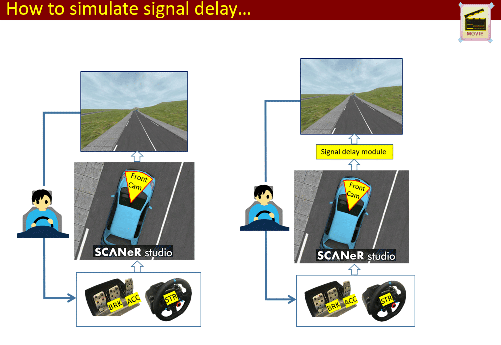
The developed software mentioned above is an executable module for SCANeR. To describe how the software introduces temporal delays to vehicle control signals and camera sensor data, here take a look at the flow of these signals and data when the software is activated during the run process of a scenario. A SCANeR user maneuvers a vehicle model through an interface equipped with a steering wheel and a gas and break pedal. Vehicle control signals are generated by the interface and are put into a buffer provided by the software in which these signals are kept for an amount of time set by the software before they are sent to the model handler module provided by SCANeR which defines the movement of the vehicle model. During its movement, video data are continuously captured by a camera sensor attached to the model vehicle and are put into another buffer provided by the software in which these data are kept for an amount of time set by the software before they are sent to the camera sensor module provided by SCANeR which is responsible for displaying the camera sensor data as a video stream on a computer screen. Through the two buffers, the software can delay the vehicle control signals and camera sensor data respectively. The buffering period can be set at a temporal grain size of a millisecond and can be changed frequently up to 1Hz.
Real world latency data can be acquired by recording the RTTs of ping packets. In our case, 3 sets of such data were obtained using a commercial software PingPlotter [1]. The first latency data set consists of RTT records for ping packets being sent to a server located 20km away from a smart phone. The second latency data set was collected by ping packets being sent to a server located 1,500km away from the smart phone. The third latency data set was acquired by ping packets being sent to a server located 18,000km away from the smart phone. In all cases, the smart phone had an LTE link to one of available base stations and RTTs were recorded for a time period of 600s. The mean latency of the first data set is 52ms and its standard deviation is 10ms. The mean latency of the second data set is 68ms and its standard deviation is 9ms. The mean latency of the third data set is 321ms and its standard deviation is 5ms.
To discover what kinds of problems we face when a vehicle is teleoperated over cellular networks inevitably having a certain level of communication delays, guiding line tracing simulations have been performed. In these simulations, a SCANeR user is expected to drive a vehicle model at a constant speed of 100km/h in such a way that a guiding line painted at the middle point of a track is kept to appear around the midpoint of the vehicle’s hood. The track is composed of 5 segments including 2 straight lines, 2 clothoids and 1 arc where the ends of the track are the straight lines whose adjacent neighbors are the clothoids. The arc is placed between the clothoids and the projected lines from the straight lines are crossed each other at an angle of 90 degrees. In this guiding lane tracing scenario, the deviation of the centroid of the vehicle from the guiding line is calculated and recorded every time when the vehicle moves forward by 0.2m. It has been found that deviations become quite large when the user drives the vehicle under the third latency data set compared to the first and send latency data sets. In other words, we cannot drive a vehicle at a speed of 100km/h in the real world if we try to teleoperate the vehicle from such a distant location as 18,000km away. For the cases of the first and second latency data sets, deviations are not so different from those obtained when no communication delays are applied.

QUOTE/ KEY NUMBERS
[1] PingPlotter, https://www.pingplotter.com/
NEXT STEPS
We plan to step forward to utilize ADAS sensors for vehicle teleoperations. For instance, by implementing a pavement markings detection algorithm in the camera sensor module of SCANER, deviations caused by communication delays might be lowered.