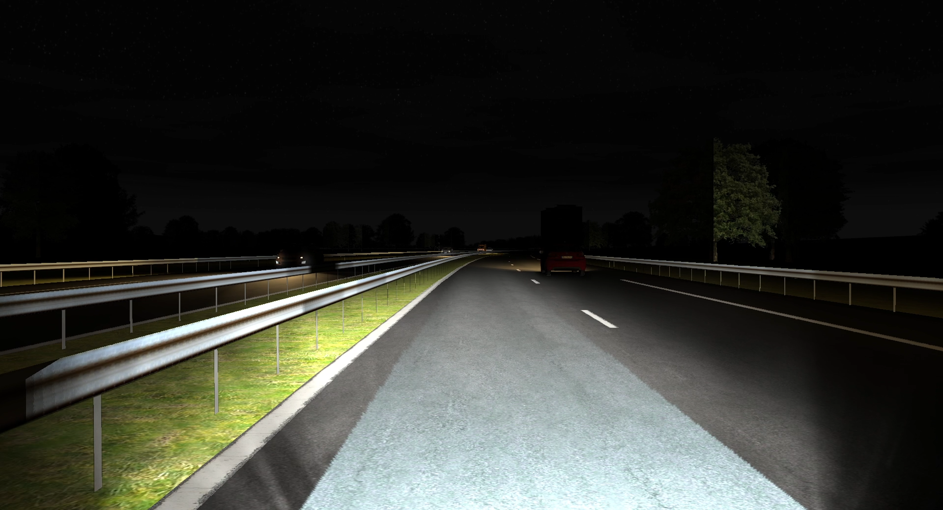
Only 25% of automobile travel occurs at night, but more than 40% of serious accidents (fatal or involving serious injury) occur during this time*.
* Data from the National Highway Traffic Safety Administration (NHTSA) and the European Commission (EC).
The industry has made significant progress in Advanced Front-lighting Systems (AFS) with the advent of Pixel Lighting. This technology significantly improves the safety of drivers, passengers and pedestrians.
However, is it possible to do Pixel Lighting with SCANeR? Of course, the most complete software on the market allows to work on all aspects of automotive simulation, including headlights. We will see in this use case how it is possible to achieve this technical prowess in SCANeR.
Prerequisites
Creating a Matrix Beam or Pixel Lighting in SCANeR requires two packages:
- The Healights pack, which is intended for OEMs and manufacturers who work in the field of lighting, especially in the development of car headlights. The purpose of the lighting simulation is to assist engineers in the evaluation, comparison, and development of different headlamps. From the design to the validation phase, the Headlights package can be used to perform real-time lighting tests with precision.
- The AD/ADAS pack, which is intended for engineers in charge of testing and validating advanced driver assistance systems and/or researchers who wish to study driver behavior when using ADAS. It provides engineers with all the functionalities to simulate functional sensors in order to provide a reliable target list for ADAS. It also provides researchers with ready-to-use solutions to simulate autonomous vehicle behavior in order to focus on driver behavior.
With the Headlights pack, it is possible to define the headlights and their light sources. The photometry of a light source and its position are defined in their photometry file. Each light source has its own photometry file (.IES, .HLT, etc.).
It is then possible to switch off, control (Intensity, Heading, Pitch, Roll) each light source with a LED Driver.
Figure 1 - SCANeR documentation about headlamps.
With the AD/ADAS pack, L1 sensors can be used to detect targets within their range. This package includes the following functional sensors: LiDAR, Camera (logical and photorealistic), Radar, Lighting, Ultrasonic and E-Horizon. Each type of sensor has a complete graphical interface for its customization.
Figure 2 - Detection of targets thanks to a logic camera.
Matrix Beam vs Pixel Lighting
A Matrix Beam is a type of projector grouping all its light sources in the form of a matrix of LEDs. This system is coupled with a camera sensor. Each LED can be turned on/off independently of each other, to avoid glare from surrounding vehicles, or to dim the light illuminating a panel to avoid glare from reflected light to the driver.
Figure 3 - Simplified schema of a Matrix Beam
Pixel Lighting can be thought of as a high-resolution Matrix Beam. Like a Matrix Beam, this system allows for finer attenuation of light on areas that may dazzle other vehicles. But it can also project patterns on the ground to assist the driver:
-
- Communication with other vehicles,
- Projection of pictograms on the ground,
- Highlighting of lines on the ground,
- Marking of safety distances,
- etc.
Figure 4 - Pixel Lighting in SCANeR
How does it work in SCANeR?
Matrix Beam
In a Matrix Beam system, each LED in the matrix is described by a light source with its own photometry. Each LED is visible in the Night Test tree.
Thus, each LED can be controlled:
-
- Manually via the NightTestManager GUI
- Via a Simulink model. Two APIs are available:
- SCANeR API: access to simulation data (list of vehicles, targets detected by sensors, environmental parameters, etc.),
- AFS API: access to additional parameters from the scenario (road curvature, etc.), and control of LEDs in orientation and intensity.
Simulink models can be used as interfaces for:
-
- Thanks to the SCANeR API: feed client control laws via a dedicated com (UDP, CAN, etc).
- Thanks to the l’AFS API: send to the SCANeR visual the new intensity/orientation of the LEDs of the matrix.
Figure 5 - Architecture diagram of a Matrix Beam in SCANeR
Pixel Lighting
In a Pixel Lighting system, the system resolution is too high for each pixel to be a light source.
In this case, the system can be seen as a single light source projecting a dynamic image.
As with a Matrix Beam system, the SCANeR API allows a client model to access the simulation data to feed an image generation model. Once the image is generated (full photometry or pictogram), it is passed to the visual via the Image Sharing API which will combine/replace the original photometry of the Pixel Lighting system via a plugin in the visual.
Figure 6 - Architecture diagram of a Pixel Lighting in SCANeR
What’s next?
You want to create your own Matrix Beam or Pixel Lighting strategy in a rich and representative world? Contact us, we will be happy to help you with your project.
If you don’t know SCANeR, come and try it for free with our trial version. Pre-sales engineers will accompany you throughout the evaluation to answer your questions and support you.


